QA Tron

A radiation therapy quality assurance and commissioning device that measures beam parameters such as beam shape and position in real time, using a scintillator, a precision two-mirror periscope, and a calibrated camera. Made in collaboration with Leo Cancer Care.

QA Tron enclosure rendered in transparent view with a green beam line passing through the scintillator volume and exiting the device.
The beam enters, the scintillator converts it to light, and the periscope carries the image to the camera, all inside one sealed enclosure.

One device. Every daily check.

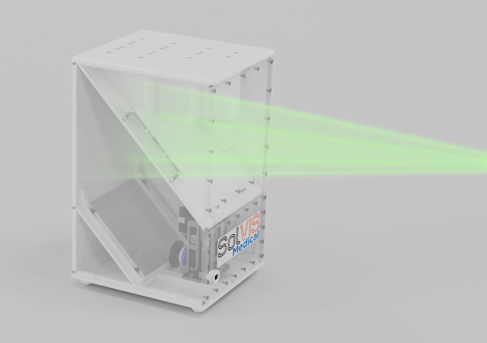
Most radiation therapy facilities run their daily QA using four sequential setups: a CT phantom, an IGRT target, a surface-guidance phantom, and one or more beam-dosimetry tools. The industry is lacking a comprehensive device that can do all these in one setting. QA Tron consolidates the entire daily QA chain of events into one radio-translucent instrument that connects with the control computer using a single PoE cable.

Integrated, not assembled

The CT phantom interface, the surface-guidance fiducials, the energy-degrading wedges, and the scintillator dosimetry chain share one coordinate frame inside one enclosure. No phantom stack to assemble each morning. No jig to maintain. No inter-device transitions.

Radio-translucent by design

The upper region is built from low-Z materials (Delrin, carbon fiber, acrylic mirrors), so the same hardware passes through CT as an unremarkable phantom. Conventional ion-chamber dosimetry phantoms can't meet this requirement.

Three proton beam energies in one delivery

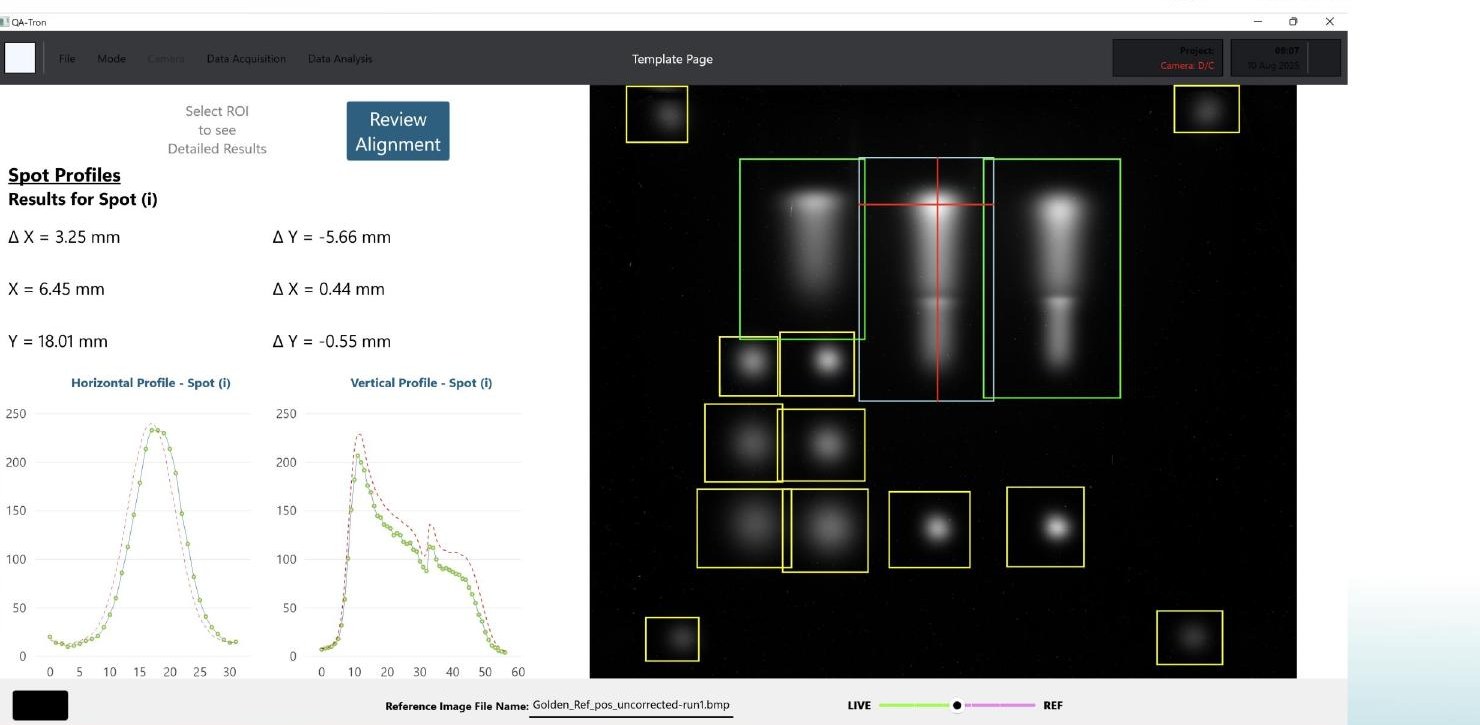
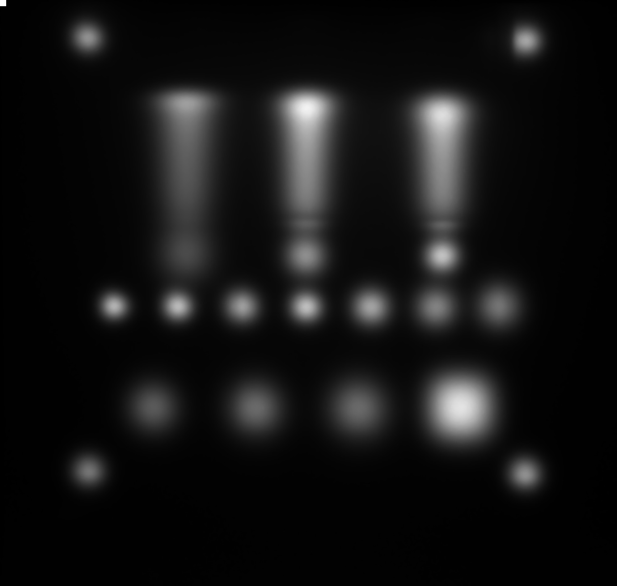
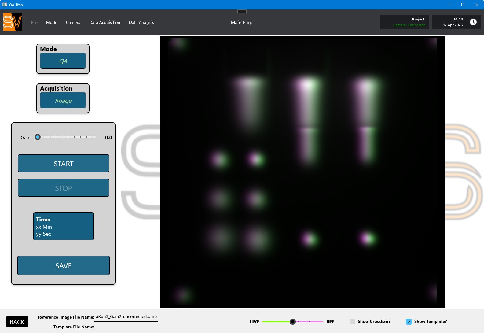
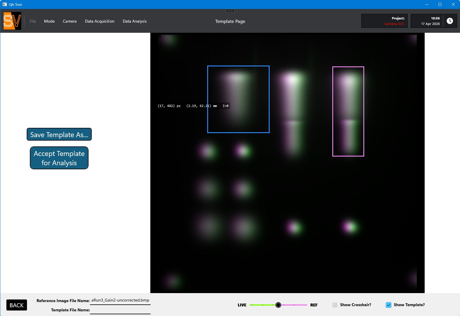
Three integrated polyethylene wedges produce three Bragg-peak measurements in a single beam delivery. Beam energy is verified across the clinical range.

One cable, one mount

A single CAT-6 PoE cable carries power and data. For upright systems, the backrest QA shelf installs the QA Tron reproducibly into position on the UPPS every day. For supine tables, the QA Tron simply rests on the patient couch.

QA-Tron control software

Built around efficiency.

Every beam parameter QA Tron measures is processed instantly and compared against set tolerances. The operator sees a summary view indicating which parameters passed, are borderline, or failed. The daily go / no-go decision comes from a single review screen.

QA-Tron control software showing the Spot Profiles analysis panel with horizontal and vertical Gaussian fits, real-time spot measurements, and the ROI template overlaid on a live scintillation image with three Bragg peaks and surrounding spot grid.
QA-Tron Data Analysis. User-defined ROIs (square for spots, rectangular for Bragg peaks) are overlaid on the live image. The software returns per-spot centroid, width, and live-vs-reference deltas in real time.
01

Two operating modes

Daily QA Mode compares live measurements against a stored golden reference and color-codes go / no-go per metric. Precision Mode saves raw images for commissioning, reference data, and annual QA.

02

Automatic image pipeline

Every frame is background-subtracted, denoised with a 5-pixel median filter, lens-distortion-corrected, and scaled to millimeters at the scintillator plane, before any analysis runs.

03

Real-time spot analysis

Every spot in a user-defined region is fit to a rotated 2D Gaussian. The software returns centroid, σₓ, σᵧ, rotation angle, and amplitude, with live vs. reference profile overlays on both axes.

04

Three-energy Bragg peak in one frame

Rectangular ROIs over the three wedge regions extract distal R₅₀% in a single acquisition. Peak position and distal edge shifts reported against the reference for all three energies simultaneously.

05

User-configurable tolerances

Every tolerance (spot centroid, spot width, intensity, R₅₀% shift, magnification) is set from a dedicated configuration tab. Color-coding on the summary view reflects each facility's own thresholds.

06

Data export

All calculated metrics export as CSV or text for downstream analysis, archival, or feeding into the facility's QA reporting system. Raw images can be saved alongside for audit traceability.

What QA Tron verifies in one setup

Every category of daily QA, addressed by one device.

01

CT image quality & HU accuracy

Radio-translucent upper region passes through the CT volume as an unremarkable low-Z phantom. Embedded CT contrast features support routine image-quality QA in the same coordinate frame as every other test.

02

IGRT registration accuracy

Applied positioner offsets (X = 4 mm, Y = 8 mm, Z = 10 mm, rotation = 1°) recovered via CT registration and compared against tolerance bands. Sub-millimeter agreement validated on PBS proton systems.

03

SGRT / optical-surface registration

External 1 mm fiducials are recovered by the room's surface-guidance system as an independent cross-check on the same applied offsets. Works with OGTS, C-Rad, Vision RT, and equivalents.

04

Beam spot position & size

2D Gaussian fits return centroid and σₓ, σᵧ for every spot in a user-defined region. Compared against a stored golden reference and color-coded against user-configurable tolerances.

05

Beam energy via Bragg peak

Three integrated polyethylene wedges produce three simultaneous relative Bragg-peak curves at three energies. Distal R₅₀% shift gives proton range with sub-millimeter sensitivity.

06

MU linearity & output constancy

Analytical volume under the fitted Gaussian (2π · a · σₓ · σᵧ) is linear in MU and independent of beam energy, robust to small spot-shape variations that distort peak-intensity measurements.

07

UPPS positioning & reproducibility

Backrest QA bracket indexes the device to the same interface as the patient backrest, removing room re-survey from daily setup. Residual offset after correction confirmed below 0.5 mm and 0.2°.

08

Laser-to-imaging coincidence

Sub-millimeter centroid extraction from a delivered spot grid quantifies the vector from radiation isocenter to the room lasers.

Scientific basis

Peer-reviewed and academically validated.

QA Tron's design and sensitivity are documented in two papers and a graduate thesis, with performance measured on a clinical pencil-beam scanning proton system and benchmarked against a commercial TPS.

  1. Technical Note

    Design and specifications of a multi-purpose radio-translucent daily quality assurance device for integrated upright proton therapy

    Schreuder N, et al.

    Journal of Applied Clinical Medical Physics · Thompson Proton Therapy Center, Knoxville, TN

  2. Sensitivity Study

    Sensitivity testing of a novel multi-purpose proton commissioning and quality assurance device

    Shanks R, et al.

    Manuscript in preparation · University of Tennessee, Knoxville

  3. M.S. Thesis

    Sensitivity Testing of a Novel Multi-Purpose Proton Commissioning and Quality Assurance Device

    Shanks R.

    Master of Science, Department of Physics, University of Tennessee, Knoxville · October 2025

Validated performance

Peer-reviewed sensitivity, measured on a clinical PBS system.

Sensitivity validation was performed at the Thompson Proton Therapy Center on an IBA ProTeus Plus pencil-beam scanning proton system, against the RayStation treatment planning system. Results below are reported in Shanks et al. (2025) and the companion technical note by Schreuder et al.

0.28 mm X-axis residual on baseline-return After 2 & 4 mm applied PPS translations · within PPS resolution
R² ≈ 1.0 ΔR₅₀% linearity vs solid water Slopes 0.998 (150 MeV) and 0.988 (180 MeV) against nominal slab thickness
< 2% SAD recovery vs commissioned values 1920 mm horizontal vs 1960 mm commissioned · 2380 mm vertical vs 2330 mm
0.32 mm QA-mode spot-size offset vs reference Constant scatter offset, zero offset required in Precision Mode
Linear MU response, energy-independent Volume-under-Gaussian metric. Three energies overlay within scatter.
~ 1 mm R₅₀% shift per 0.5° pitch With negligible change in spot position. Clean setup-error diagnostic.
Actual scintillation light measurement showing three Bragg peaks behind the energy-degrading wedges, with the surrounding spot grid used for sub-millimeter position analysis.
Actual measurement. Three-energy Bragg peaks plus the surrounding spot grid used for sub-millimeter position analysis. IBA ProTeus Plus PBS proton system, Thompson Proton Therapy Center.
The QA Patient workflow

Daily QA that mirrors a complete clinical treatment.

QA Tron supports a workflow we call the QA Patient: a daily verification that touches every subsystem the clinical workflow depends on, in the same order, with the same software paths, just with the QA Tron in the chair instead of a patient.

  1. 01

    Safety checks & OIS login

    Room interlocks and AV verified. Operator logs into the OIS / Leo Control System and selects the QA Patient.

  2. 02

    Mount & deliberate offset

    QA Tron installs on the UPPS via the backrest QA bracket. Positioner moves to a deliberately offset imaging position (X = 4 mm, Y = 8 mm, Z = 10 mm, rotation = 1°).

  3. 03

    CT + IGRT registration

    CT acquisition and registration against the reference CT. Recovered correction vector compared against the applied offsets. CT image quality verified in the same scan.

  4. 04

    SGRT independent recovery

    OGTS (or equivalent surface-guidance system) recovers the same applied offsets via the external 1 mm fiducials, an independent cross-check against the IGRT result.

  5. 05

    Apply correction & verify

    Correction applied via the hand pendant, second CT acquired, residual-offset check confirms positioner accuracy below 0.5 mm and 0.2°.

  6. 06

    QA beam delivery

    Spot positions, beam energies via three-wedge R₅₀%, and cumulative output verified against the golden reference. One screen, color-coded go / no-go.

Designed for integration

Interfaces with the systems your facility already runs.

QA Tron does not require a vendor lock-in, custom protocol, or proprietary control bus. It speaks the same languages your existing hardware and treatment planning system already speak.

Patient positioner

Leo Cancer Care MARIE / UPPS. Backrest QA bracket uses the same indexing interface as the patient backrest. Compatible with conventional couch-based PPS through the seat-column QA platform.

Treatment planning system

Validated with RayStation. CT data imports natively; PLD plans designed against the device CT ensure planned spot grids fall on the scintillator.

Surface guidance

OGTS · C-Rad · Vision RT · or any commercial SGRT system that recognizes external 1 mm fiducials on the device exterior.

Imaging

Vertical or horizontal diagnostic-quality CT · CBCT · planar kV. Radio-translucent upper region means no high-Z artifacts in the IGRT image set.

Beam delivery

Pencil-beam scanning proton systems (validated on IBA ProTeus Plus). Platform-neutral. Any PBS system that can deliver a defined spot pattern is supported.

Connectivity

Single CAT-6 connection carries power and data to the PoE camera. Pre-provisioned Triax line for a future in-beam ionization chamber.

Software runthrough

From beam-on to result in four steps.

The QA-Tron control software runs the full daily workflow on one screen: connect, acquire, compare against your reference, and read the deltas. Three operating modes (QA, Precision, and Offline review) cover the daily check, commissioning-grade analysis, and after-the-fact review of saved images.

QA-Tron main page with the camera connected, showing a live color scintillation image of three wedge columns and the surrounding spot grid.
1 · Acquire. Connect to the in-box camera over the single network cable, set gain, and start. The live scintillation image streams to the main page with connection status always visible.
QA-Tron template page with rectangular ROIs drawn around wedge regions on the scintillation image, with Save Template and Accept Template for Analysis buttons.
2 · Template. Draw regions of interest directly on a reference image, with live pixel and millimeter readout under the cursor. Save the template once and reuse it every day.
QA-Tron manual alignment dialog with up/down, left/right, Z, and roll controls, displayed X/Y/Z shift and roll values, and a magenta-green overlay of live versus reference images.
3 · Align. Auto or manual registration against the reference. The overlay view shows residual misalignment at a glance, with X, Y, Z shift and roll reported in millimeters and degrees.
QA-Tron spot profiles analysis panel showing reference versus current position and sigma for a selected spot, color-coded deltas, and measured-versus-reference Gaussian profiles in X and Y.
4 · Analyze. Per-spot position and sigma against reference, with color-coded deltas and measured-vs-reference Gaussian profiles. Select any ROI for detailed results and export with one click.

Get QA Tron in your facility.

Pricing, lead time, and integration with your imaging and reporting systems.